Watch the Video
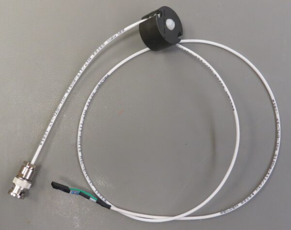
Many inquiries have been made about measuring the output current on the PCO-7114 pulsed laser diode driver modules. In the following article the proper current measurement technique will be explained. In this demonstration the PCO-7114-50-4 will be used and will be tested into a shorted load. The current monitor cable is a PCA-9140 and can be purchased from Directed Energy Inc. The following picture is the PCA-9140 current monitor cable.
The PCO-7114 50-4 is a 50 A 4 ns fixed pulse width laser diode driver that has a pulse frequency of up to 650 kHz depending on the output current. The output current can be adjusted by changing the input high voltage.
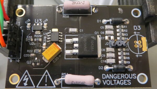
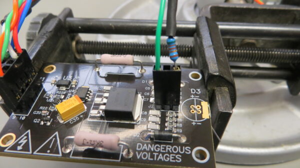
The picture above shows the PCO-7114 50-4 module. To measure the current, first locate J2, the current monitor connector. The positive pin (center connector of the coax cable) is to the left and is where the series 50Ω resistor on the PCA-9140 current monitor cable is located. In the following picture you can see this cable connected to J2.
The next step is to connect the cable to the oscilloscope. You will need to make sure the oscilloscope input is terminated into 50Ω. Most oscilloscopes have this option built in, but if yours does not, you will need a 50Ω termination connector. The next step will be to set the oscilloscope’s horizontal and vertical scales to properly see the current pulse. In this demonstration the settings are horizontal at 4 ns per division and vertical at 500 mV per division. The scaling for the PCO-7114 50-4 is 500 mV per 10 A. The oscilloscope being used is a Tektronix DPO 4102B-L with 1 GHz bandwidth.

The PCO-7114 50-4 is a 50 A 4 ns fixed pulse width laser diode driver that has a pulse frequency of up to 650 kHz depending on the output current. The output current can be adjusted by changing the input high voltage.

The picture above shows the PCO-7114 50-4 module. To measure the current, first locate J2, the current monitor connector. The positive pin (center connector of the coax cable) is to the left and is where the series 50Ω resistor on the PCA-9140 current monitor cable is located. In the following picture you can see this cable connected to J2.

The next step is to connect the cable to the oscilloscope. You will need to make sure the oscilloscope input is terminated into 50Ω. Most oscilloscopes have this option built in, but if yours does not, you will need a 50Ω termination connector. The next step will be to set the oscilloscope’s horizontal and vertical scales to properly see the current pulse. In this demonstration the settings are horizontal at 4 ns per division and vertical at 500 mV per division. The scaling for the PCO-7114 50-4 is 500 mV per 10 A. The oscilloscope being used is a Tektronix DPO 4102B-L with 1 GHz bandwidth.
The next step is to pulse the load and monitor the output current. In the next picture the complete setup is shown.
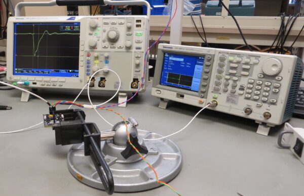
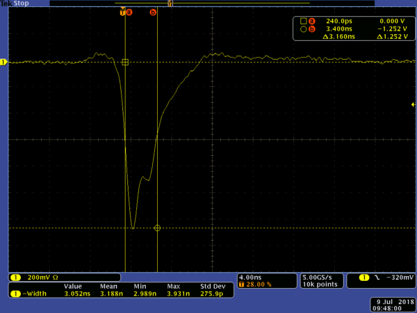
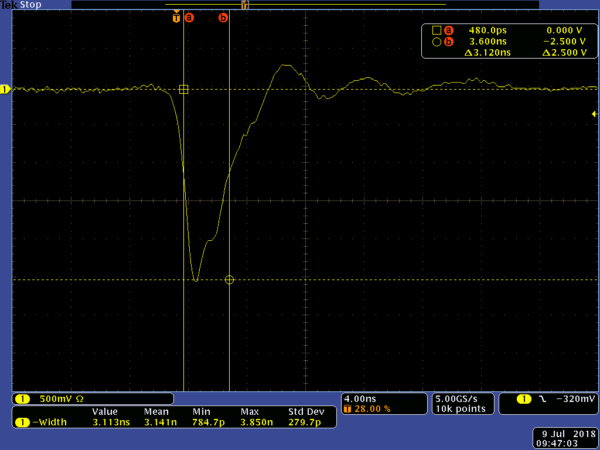
The next two pictures show the current waveform measured on the oscilloscope. The first one is at 25 A peak with a 3.1 ns pulse width. The second is at 50 A peak with a 3.1 ns pulse width. In both examples the pulse width is measured at Full Width Half Maximum (FWHM).
If you need further assistance or have any questions regarding this article or the PCO-7114 50-4 and the PCA-9140 current monitor cable, please call (970) 493-1901 or email us at support@directedenergy.com
Thanks for reading! If you have additional questions please contact us!


