PCO-7125 | 5A 30ns Pulsed Laser Diode Driver Module

Request For Quote

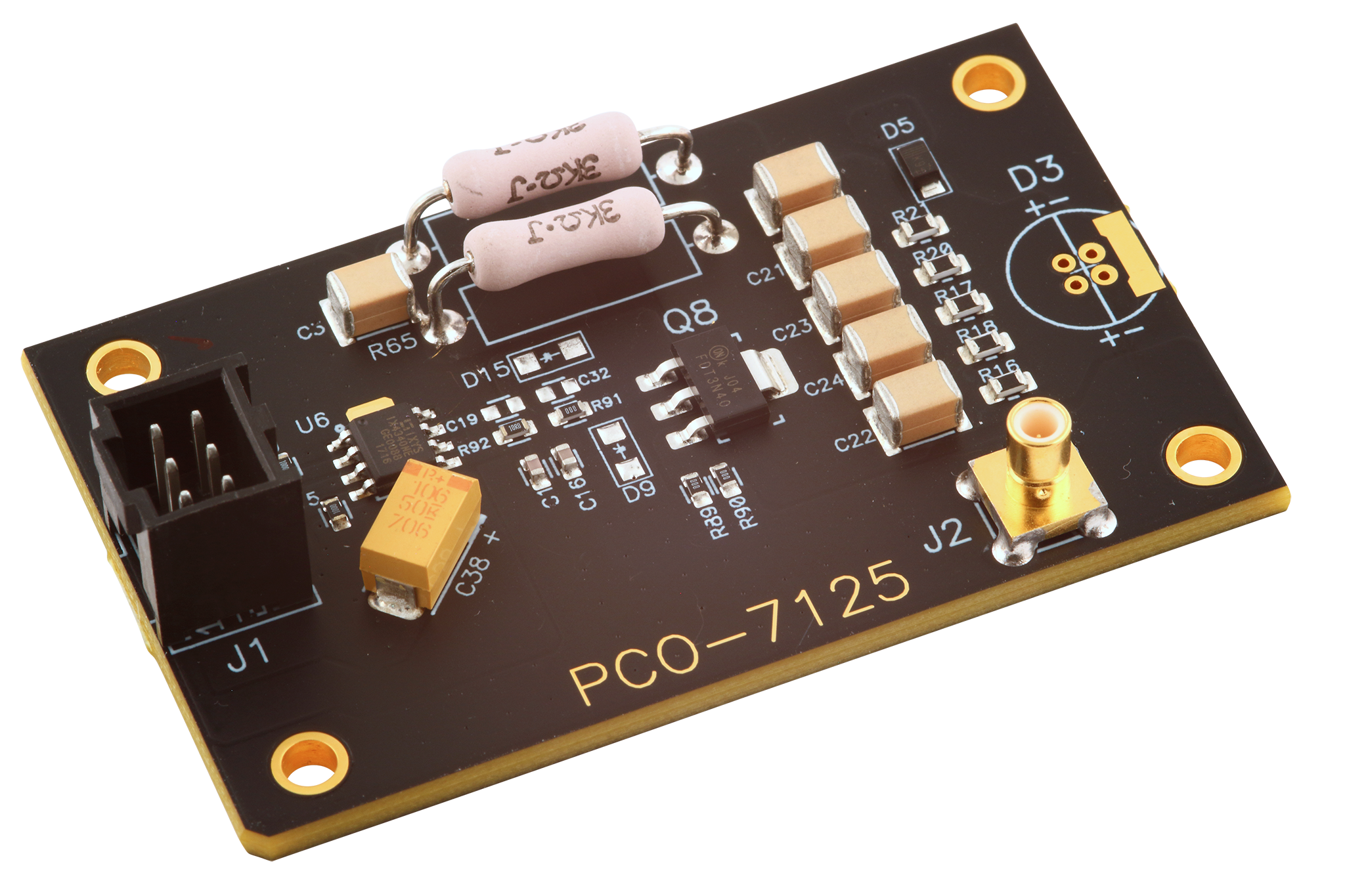
The PCO-7125 is a compact and economical OEM pulsed-current laser diode driver module.

GET QUOTE

The PCO-7125 is a compact and economical OEM pulsed-current laser diode driver module. It is designed to provide extremely fast high-current pulses for driving laser diodes in range finder, LIDAR, atmospheric communications and other applications requiring high-current nanosecond pulses. This module offers variable output current from 500 mA to 5000 mA with pulse widths from 34 ns to 1 μs at frequencies up to 865 kHz.

Mounting pads are provided to mount the laser diode directly to the driver. The four-hole mounting pattern accepts TO-18, TO-5, TO-52, 5.6 mm, and 9 mm packages.

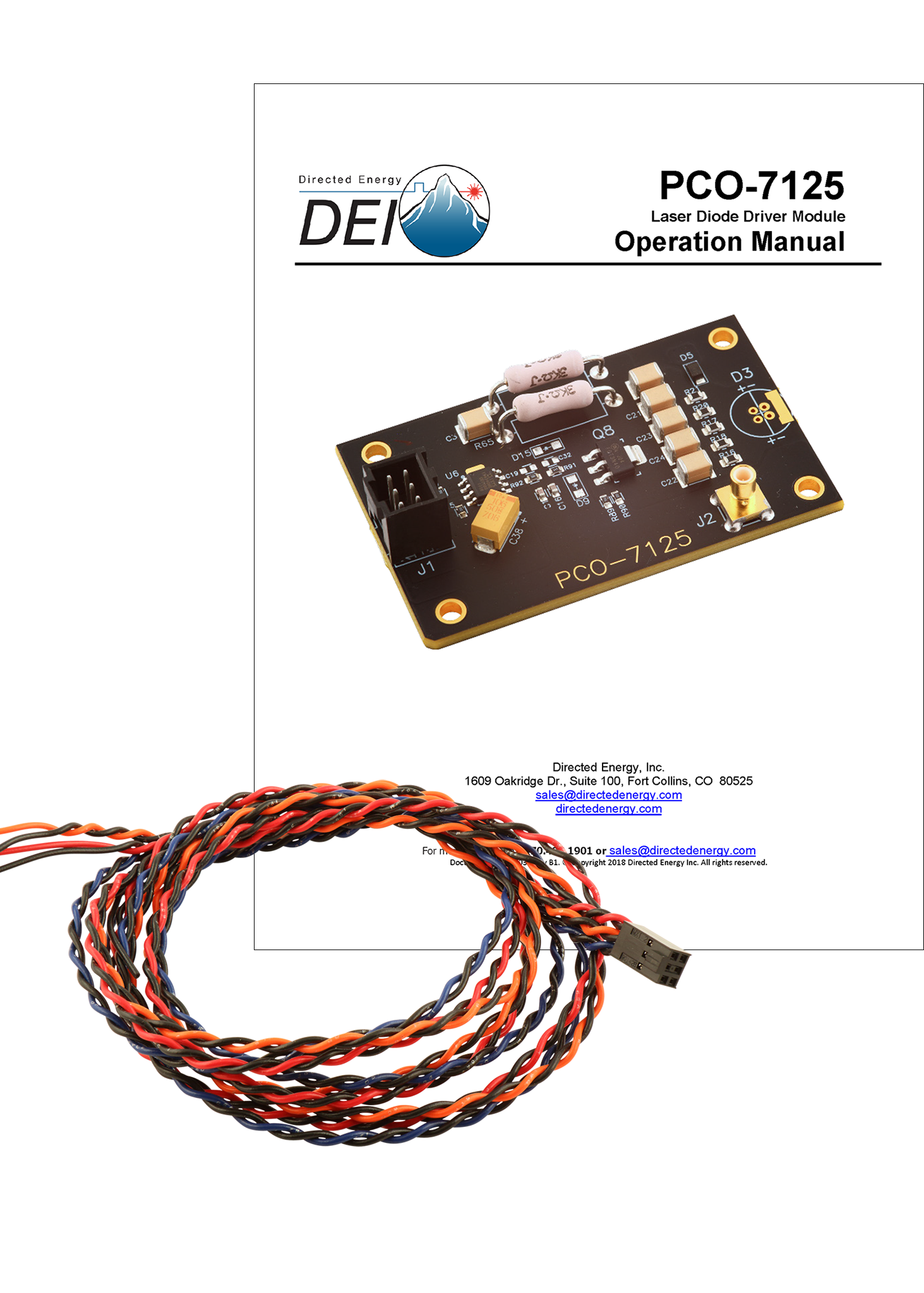
The DC high voltage and +12 VDC power supplies are connected via J1, a six-pin male header connector, using the supplied control cable. Pulse current depends on HV supply voltage over the range of 0 V to +200 V (maximum). Externally-generated pulses are fed to the gate input via J1. The width and repetition rate of the gate pulses directly set the timing of the output pulses.

A current monitor output is provided to observe the diode current in real time with an oscilloscope.

Four mounting holes are provided.

Features
  • Continuously Adjustable Pulse Width from 34 ns to 1 µs
  • 500 mA To 5 A Output
  • Pulse Repetition Frequency To 865 kHz
  • Pulsed Current Monitor Output
  • 34 nS Minimum Pulse Width
Applications

The PCO-7125 is designed to provide extremely fast high-current pulses for driving laser diodes in:

  • Range finders
  • LIDAR (Light Detection And Ranging)
  • ADAS (Advanced driver-assistance systems)
  • Other applications requiring high-current nanosecond pulses
Compliance Voltage

5V

Max Current Amplitude

5A

Rise/Fall Time

17ns

Max Frequency

865 kHz

Pulse Engine (Trigger)

External

Remote Control

N/A

Form Factor

Module

Cooling

Ambient Air

Pulse Width

30 ns to 1000 ns

Maximum High Voltage Input

200 V DC, 100 mA, ≤ 25 W *1

Shipping Dimensions (in)

12x9x4

Shipping Weight (lbs)

1


Product
(1) PCO-7125 Laser Diode Driver Module

PCO-7125 Series Accessory Kit
(1) PCA-7000 Control Cable
(1) Operating Manual

Current Monitoring Theory

We prefer to measure current going through the laser diode rather than the voltage across it. The voltage as measured across the diode is difficult to filter for the noise present in the signal.

Using the installed current monitoring circuit (J2)

The PCO-7125 contains a group of very low value resistors in series with the laser diode. The resistors convert the current to a small voltage that is easily viewed with an oscilloscope and this signal is connected to J2.

Ordinary oscilloscope probes have too much unshielded wire and thus pick up too much noise from the heavy switching currents. To overcome this we offer the PCA-9245 Current Monitor Cable. With the PCA-9245 you simply set your scope to 50 Ω termination or if your oscilloscope does not have this option, use a 50Ω terminator at the input of the oscilloscope and plug the current monitor into J2 on the PCO-7125. The PCO-7125 current monitor output is 50 ohms.

The Current pulse will be displayed on the oscilloscope at 500 mV per amp.

The PCO-7125 is designed to operate safely into an open so it won’t be damaged if the diode opens during operation or if the unit is operated without a diode attached.

The PCO-7125 requires two support voltages:

  1. +12 VDC at 80 mA
  2. High voltage supply of +50 to +200 V at 125 mA or 25 watts.

The benefit of using a gate input with an impedance of 50 Ohms is that a low-input impedance reduces false triggering from noise.

If you’d like to convert the PCO-7125 gate input to high-impedance, you can remove R15 and R19 (100Ω resistors in parallel). However, this configuration may result in unpredictable pulse output.

The ideal pulse shape for many applications is a perfect square… here’s why the edges are not perfectly square:

The PCO-7125 “rise time” and “fall time” specification is <17 ns typical as measured from 10% to 90% of the full waveform. That means the rise time and fall time is measured between two points on the curve, one at 10% of maximum current and the other at 90% of maximum current. The trace below has to have an 11 ns  rise time and 14 ns fall time. Any added inductance to the output such as strip line or long leads on the diode package would increase this rise and fall time. This will also affect the minimum pulse width and the shape of the pulse.