
What a voltage pulser is and how to specify one
A voltage pulser takes energy from a DC supply, stores it, and on a trigger releases it as a constant-voltage, high-peak-current pulse into a load. This primer covers what the loads are, what is inside the instrument, which six specifications decide whether a model fits, and what to send when asking for one.
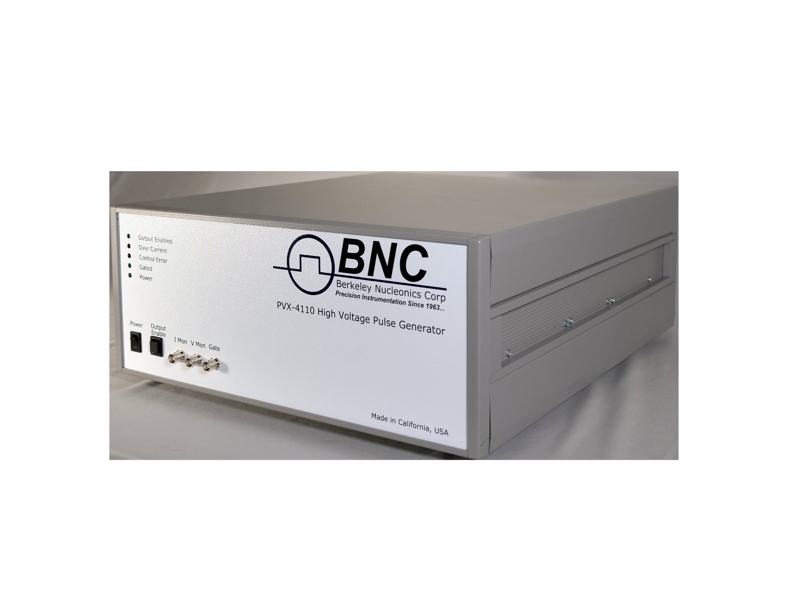
Photo: PVX-4110

1What a voltage pulser drives
Pulsers with maximum output voltages from tens of volts to 10,000 V are used for accelerated life testing of dielectric materials; for driving extraction grids and deflection plates in time-of-flight mass spectrometers and accelerators; for pulsed current-voltage characterization of semiconductor devices; and for driving Pockels cells, Q-switches, microchannel plates, acoustic transducers, image intensifiers and photomultiplier tubes. The load is usually connected through several feet of coaxial cable.
Most of these loads are capacitive: a Pockels cell, a deflection plate or a microchannel plate looks electrically like a small capacitor, typically tens to hundreds of picofarads with its cable. Some pulsers are designed for 50 Ω resistive loads instead, and a few applications, such as pulsed I-V testing, present a device that conducts during the pulse. Pulsers are generally not intended to drive plasma chambers or other loads that become a short or near short during operation, although the output stage is protected against an arc or a short at the load.
2Capacitive loads: current on the edges, power from the rate
A capacitive load draws current only while its voltage is changing, so the current flows on the edges of the pulse and the flat top draws almost nothing. The peak current follows from
A 100 pF load (the cell plus its cable) stepped by 1,000 V in 25 ns draws 100 pF × 1,000 V / 25 ns = 4 A for the duration of the edge. That is why a pulser rated for a few milliamperes of average current is built to deliver amperes on each edge.
Each charge and discharge of the load dissipates energy in the pulser's output stage, so the average power rises with the repetition rate:
The same 100 pF at 1,000 V and 10 kHz dissipates 100 pF × (1,000 V)² × 10 kHz = 1 W. At 10,000 V the square in (2) makes that 100 W, which is the maximum average power rating of the PVX-4110 and the reason its 10 kHz limit at full voltage applies to a 100 pF total load. (1) and (2) together decide which model a capacitive load needs; the note Capacitive-Load Pulsing works through both in more depth.
3What is inside a pulser
At minimum a voltage pulser contains three things (Figure 1): a fast high-voltage electronic switch that creates the pulse edges; a local capacitor bank that stores energy between pulses and releases it during the pulse; and a logic-level trigger (gate) input that controls the pulse width and the repetition rate. The Directed Energy PVX and PVM models use a direct-coupled half-bridge, often called a totem-pole output stage: two high-voltage switches in series between a high rail and a low rail, with the gate deciding which rail is connected to the output. The pulse amplitude is the difference between the two rails, and the width and rate follow the gate.
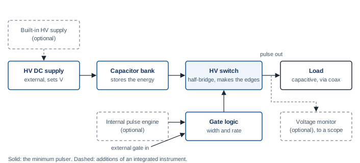
A more integrated pulser adds an internal pulse engine that generates its own trigger pulses, a voltage monitor that scales the output for an oscilloscope, and a built-in high-voltage DC supply to recharge the energy-storage capacitors. Modules such as the PVM-1001 and instruments such as the PVX-4110 take their high voltage from an external supply; the PVX-4000-2kV and the PVM-4210 carry their supplies inside. Depending on the model, the pulses are positive only, negative only, or bipolar.
4The six specifications that matter
Six numbers decide whether a pulser fits an application, and they are the six to send when asking for one:
- Voltage. The pulse amplitude, and its polarity: positive, negative or both, and whether the pulse is referenced to ground or offset from it.
- Pulse width. The shortest and longest pulse needed. On the PVX and PVM models the width follows the gate from a minimum of tens or hundreds of nanoseconds out to DC.
- Repetition rate. The highest rate, and the duty cycle. For a capacitive load the rate and the voltage set the average power through (2).
- Rise and fall time. Specified 10 to 90 percent into a stated load. A half-bridge gives equal rise and fall; the series-resistor method in How Do I Slow the Rise Time of My Voltage Pulser? covers the case where a slower edge is wanted.
- Peak output current. The current the output stage can source and sink on an edge, from (1) for the load and cable capacitance.
- Maximum average power. The dissipation the pulser can sustain, which caps the product C · V² · F.
Table 1 gives the first four of these for the current Directed Energy line, from the datasheets.
| Model | Output voltage | Rise and fall time | Pulse width | Repetition rate | Form |
|---|---|---|---|---|---|
| PVX-2506 | 0 to +50 V, 10 A, for pulsed I-V testing | See datasheet | Under 1 μs to 100 μs, 50% maximum duty cycle | See datasheet | Benchtop instrument |
| PVM-1001-P and -N | 0 to +950 V or 0 to -950 V into 50 Ω | Under 10 ns rise (8 ns or less at 200 to 950 V positive) | 55 ns to 10,000 ns | To 1 MHz, bursts to 5 MHz | Module, external HV supply |
| PVM-4210 | 0 to +950 V and 0 to -950 V, two channels, 1,900 V differential | 25 ns or less | Under 50 ns to DC | Single shot to over 20 kHz, 5 MHz burst; 4 W per channel | Module, internal HV supplies |
| PVX-4151 | 0 to ±1,500 V | Under 25 ns, typically under 20 ns | Under 60 ns to DC | Single shot to 240 kHz at 1,500 V; 150 W maximum average power | Instrument, external HV supply |
| PVX-4000-2kV | 0 to ±2,000 V, positive plus negative not over 2,000 V | 50 ns or less from 500 V to 2,000 V | 500 ns to DC on the external trigger | Internal trigger 40 Hz to 30 kHz; external single shot to 100 kHz | Instrument, internal HV supplies, RS-232 and USB |
| PVX-4141 | 0 to ±3,500 V | 25 ns or less | 60 ns to DC | Single shot to 30 kHz at 3,500 V; 100 W | Instrument, external HV supply |
| PVX-4130 | 0 to ±6,000 V | Under 60 ns | Under 150 ns to DC | Single shot to 10 kHz at 6,000 V; 100 W | Instrument, external HV supply |
| PVX-4110 | 0 to ±10,000 V | Under 60 ns | Under 200 ns to DC | Single shot to 10 kHz; 100 W | Instrument, external HV supply |
5How to specify one
Send the load and what it is for (a Pockels cell, a deflection plate pair, a transducer, a device under test), its capacitance or impedance, the cable length to it, the voltage and polarity required and whether the pulse must be offset from ground, the pulse width range, the repetition rate and duty cycle, and the rise and fall time the application needs. From those an applications engineer can check the edge current with (1), the average power with (2), and name the closest standard model, or say plainly that the catalog does not cover it and what a custom build would involve.
Contact info@berkeleynucleonics.com or 800-234-7858. The note Selecting an HV Pulse Generator on berkeleynucleonics.com goes through the selection in more detail.
Talk to an applications engineer
Tell us your load, pulse width and repetition rate. We will point you at the right driver or pulser, or tell you plainly if we do not have one.