
How Do I Slow the Rise Time of My Voltage Pulser?
PVX and PVM series pulsers are built for speed, and the rise/fall time is fixed by the output stage rather than user-adjustable. Some applications call for a slower, more controlled edge instead. Here is how to shape it deliberately, why series resistance is the preferred method, and how to size and select the resistor.
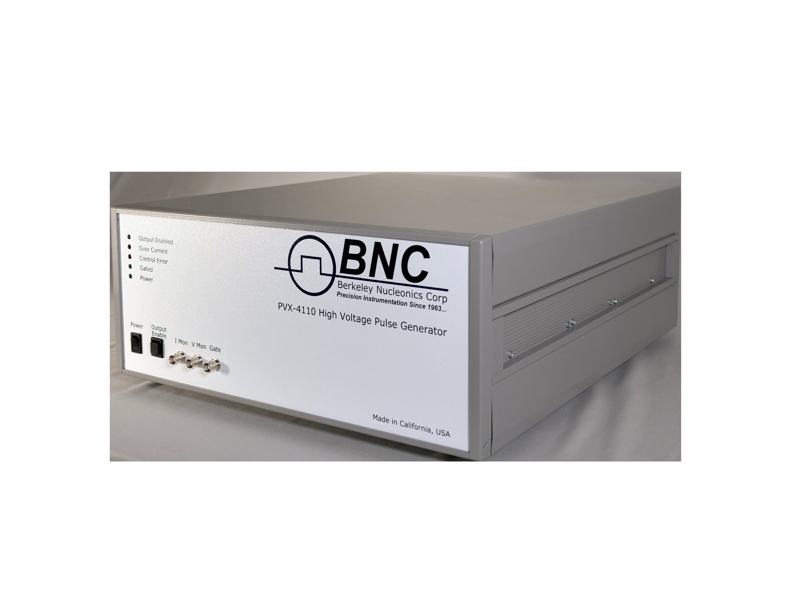
Photo: PVX-4110

1Why Slow the Edge Down
PVX and PVM series high voltage pulsers are built to drive capacitive loads as fast as the output stage allows, and that rise/fall time is not user-adjustable. Many applications use that speed in full; some need a slower edge. A device under test with its own bandwidth limit, a cable or fixture prone to ringing on a fast edge, or a load that tolerates only a gentler slew rate can all call for a deliberately slower edge than the pulser produces on its own.
The pulser cannot be reconfigured to output a slower native edge. Instead, the edge is shaped externally, between the pulser output and the load. Two approaches are commonly proposed: add capacitance at the load, or add resistance in series with it. The sections below cover why the added-capacitance approach is limited by the pulser's power-dissipation rating, and why a series resistor is the practical method.
2The Power-Dissipation Ceiling
Driving any capacitive load dissipates power according to P = C · V² · F, where C is the total load capacitance (the load itself, its cable, and the pulser's own internal capacitance), V is the pulse voltage, and F is the repetition frequency. One full charge and discharge dissipates C·V², half on each edge. The PVX models and the PVM-4210 carry a maximum average power rating for capacitive loads, and this relation sets the achievable combination of capacitance, voltage, and repetition rate before that rating is reached.
Consider the PVX-4110, rated for a maximum average power dissipation of 100 W and an internal capacitance of approximately 50 pF. At its rated maximum of 10,000 V and 10 kHz, the capacitance budget is 100 W / ((10,000 V)² × 10 kHz) = 100 pF in total, which leaves about 50 pF for the external load and cable together. Adding capacitance at the load to slow the edge eats directly into that budget: more capacitance at the same voltage and repetition rate means more dissipated power, and the voltage or repetition rate has to come down to compensate.
Maximum average power for capacitive loads: 100 W on the PVX-4110 (internal capacitance about 50 pF), PVX-4130 (about 100 pF, derated 2 W per °C above 25 °C) and PVX-4141 (about 120 pF); 150 W on the PVX-4151 (200 pF); 4 W per channel on the PVM-4210 (125 pF). The PVM-1001 is specified into a 50 Ω resistive load, where this relation does not apply.
3Added Capacitance vs. Series Resistance
Because added output capacitance is constrained by the power budget above, and because it changes the load the pulser sees (with knock-on effects on peak current and heating), it is a limited and generally less desirable way to slow the edge. Inserting a series resistor between the pulser output and the load is the preferred method. The resistor forms an RC time constant with the load capacitance, and that RC product becomes the dominant factor setting the rise time, not the pulser's internal power budget.
A series resistor has two further advantages. The energy that charges and discharges the load capacitance, C·V² per cycle, is then dissipated mostly in the resistor rather than in the pulser output stage, provided the resistor is much larger than the on-resistance of the output stage; the pulser's own internal capacitance still dissipates in the pulser. And the resistor is easy to change or remove without touching the pulser.
4The Series-RC Method
With a resistor R in series with a load capacitance C, the output edge is rounded into an exponential (Figure 1), and the standard ten-to-ninety-percent rise time follows the relation t_rise ≈ 2.2 · R · C (2.2 = ln 9). This is the same RC relation that governs cabling effects on any fast pulser output; here it is applied deliberately instead of treated as a parasitic. Solving for the resistor needed to hit a target rise time: R = t_rise / (2.2 · C).
C in this relation is the capacitance on the load side of the resistor: the device under test plus any cable between the resistor and the device. The pulser's internal capacitance, and any cable between the pulser and the resistor, sit on the source side; the pulser charges them directly, so they count toward its power budget (Section 2) but not toward the RC edge. A resistor mounted at the load leaves the cable on the source side; a resistor mounted at the pulser output puts the cable on the load side. Datasheet values for the factory cables: RG-62, 13 pF per foot (PVX-4151); Belden 8218, 21.5 pF per foot (PVM-4210); the PVX-4000 output cable, 1.57 pF per cm, about 48 pF per foot.
5Worked Example
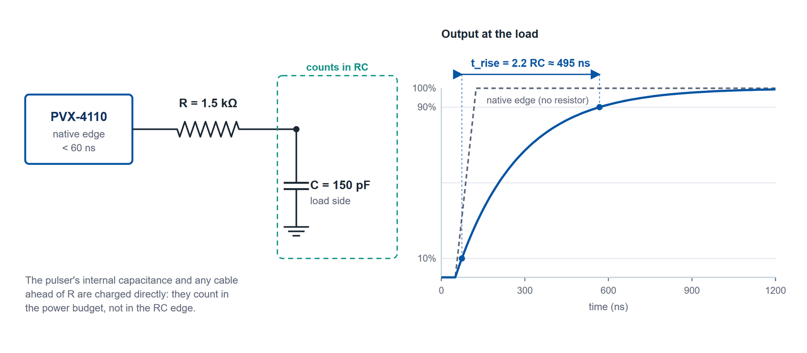
The numbers below are a worked example. They take 150 pF, the load in the PVX-4110 datasheet's minimum-pulse-width capture, as the capacitance on the load side of the resistor. Recompute for the actual load, cable, and target rise time.
Target. Suppose the application calls for a 500 ns rise time (against the PVX-4110's native edge of under 60 ns) into 150 pF on the load side of the resistor.
Solve for R. R = t_rise / (2.2 · C) = 500 ns / (2.2 · 150 pF) ≈ 1.5 kΩ.
Check. Plugging 1.5 kΩ back in: 2.2 · 1500 Ω · 150 pF ≈ 495 ns, within rounding of the 500 ns target.
Resistor power. At 10,000 V and 1 kHz, the load-side energy per cycle is C · V² = 150 pF · (10,000 V)² = 15 mJ, so the resistor dissipates 15 W. Section 8 splits that across a resistor string.
Actual rise time depends on the real load, cable length and type, resistor placement, and the resistor's own parasitics (Section 7). Measure the edge with the actual load in place.
6Resistor Voltage Rating
The series resistor sits directly between the pulser's high voltage output and the load, so it must be rated for the full pulse voltage, not just the voltage drop across it in normal operation. Standard commercial resistors are typically rated for only 100 to 350 V. If the load ever arcs, flashes over, or otherwise fails as a short circuit, the full pulse voltage from the generator appears across the series resistor almost instantaneously. A resistor rated only for a fraction of that voltage can fail catastrophically under that condition.
Select a resistor (or resistor combination, see Section 8) explicitly rated for the full output voltage of the pulser in use, not merely the voltage the resistor sees in normal, non-fault operation.
7Avoiding Parasitic Inductance
Ordinary wirewound resistors have significant parasitic inductance from their coiled construction. Inserted into a fast-edge high voltage path, that inductance interacts with the edge to produce voltage spikes, following V = L · di/dt: the faster the current changes, the larger the spike for a given inductance. At high voltage, an inductance-driven spike can be large enough to damage the resistor, the load, or the pulser output stage.
Use resistors specifically constructed to minimize inductance for this application, such as non-inductive wirewound types or thin-film resistors designed for pulse and high voltage service, rather than a generic wirewound part pulled from a general-purpose bin.
8Stacking Resistors for Higher Voltage
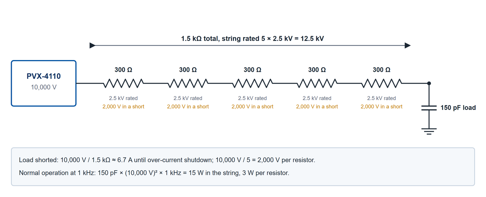
When a single resistor rated for the full pulse voltage is not available in the needed value, several lower-rated resistors can be connected in series (Figure 2). The string's voltage rating is the sum of the individual ratings, provided the resistors are equal in value so the voltage divides evenly. For the Section 5 example on a PVX-4110 set to 10,000 V, the string must withstand 10,000 V if the load shorts. With resistors rated 2.5 kV each, four is the minimum (4 × 2.5 kV = 10 kV) and five give margin (12.5 kV). Five 300 Ω resistors make the 1.5 kΩ target, and in a short each one sees 10,000 V / 5 = 2,000 V, inside its 2.5 kV rating. The fault current, 10,000 V / 1.5 kΩ ≈ 6.7 A, flows until the pulser's over-current circuit shuts the output down. In normal operation at 1 kHz the string dissipates 15 W (Section 5), 3 W in each resistor, so each needs a continuous power rating above 3 W as well as a pulse-energy rating suited to the fault.
When stacking resistors for high voltage, maintain adequate physical spacing and creepage distance between them, and follow standard high-voltage layout practice, to prevent arcing across or between the individual resistors.
Several manufacturers publish non-inductive, high-voltage resistor lines suited to this use. Check each part's continuous and pulse voltage ratings, power rating, and inductance on its own datasheet before relying on it.
9Relationship Summary
Table 1 collects the relations from this page in one place.
| Quantity | Relation | Note |
|---|---|---|
| Power dissipation | P = C V² F | Limits added output capacitance; ratings by model in Section 2. |
| Series-resistor dissipation | P_R ≈ C_load V² F | Load-side energy, dissipated in the resistor (Section 5 and Section 8). |
| RC rise time (10 to 90%) | t_rise ≈ 2.2 R C | C is the load-side capacitance: device plus any cable between resistor and device. |
| Resistor value | R = t_rise / (2.2 C) | Solve for the series resistor needed to hit a target rise time. |
| Inductive spike | V = L di/dt | Why ordinary wirewound resistors are unsuitable; use non-inductive types. |
These are standard first-order relations; exact behavior depends on the specific pulser, cable, load, and resistor parasitics. See Capacitive-Load Pulsing for the underlying physics of I = C dV/dt and the power budget, and Selecting an HV Pulse Generator for model selection.
10Talk to an Engineer
Sizing a series resistor for a real application means working from the actual load capacitance, cable length, target rise time, and pulse voltage together, and confirming the pulser's power-dissipation rating is not exceeded. A BNC applications engineer can help work through that against the specific PVX or PVM model in use.
Contact a BNC applications engineer at info@berkeleynucleonics.com or 800-234-7858.
Talk to an applications engineer
Tell us your load, pulse width and repetition rate. We will point you at the right driver or pulser, or tell you plainly if we do not have one.