
Measuring pulsed laser diode current on the PCO-6131 and PCO-6141
The output current of a PCO-6131 or PCO-6141 is measured with a current monitor board that puts a low-inductance sense resistor in the output loop and scales it for a 50 Ω oscilloscope input. This note shows the board, the connections and the scope settings, with captures at 30 A, 60 A and 125 A, and keeps the procedure for the discontinued PCO-7114 series for units still in service.
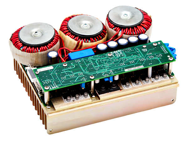
Photo: PCO-6131
1What the current monitor does
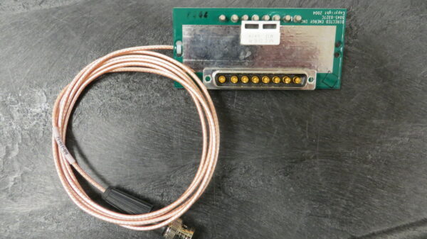
The current a driver delivers to its load is set by the driver's regulator, but the pulse shape the load receives depends on the output loop, so the measurement is made in the loop itself. The current monitor accessory is a small board that attaches to the driver's output connector and carries a current-to-voltage resistor (CVR), also called a current sense resistor, in series with the output. The voltage across it is brought out on a BNC connector scaled for a 50 Ω oscilloscope input. A sense resistor in the loop reduces the uncertainty about the current and pulse shape at the load to the tolerance of the monitor, which the datasheets give as plus or minus 3 percent of actual current.
The two drivers take different boards (Table 1). Check the board before connecting it: the scale factors differ by five to one.
| Driver | Current monitor | Scale factor into 50 Ω | Reading at full output |
|---|---|---|---|
| PCO-6131 (125 A) | PCA-9155 | 1000 A/V, which is 1 mV per A | 125 A reads 125 mV |
| PCO-6141 (60 A) | PCA-9150 | 200 A/V, which is 5 mV per A | 60 A reads 300 mV |
The demonstration that follows uses a PCO-6131 with the PCA-9155 (Figure 1).
2Fitting the board to the driver
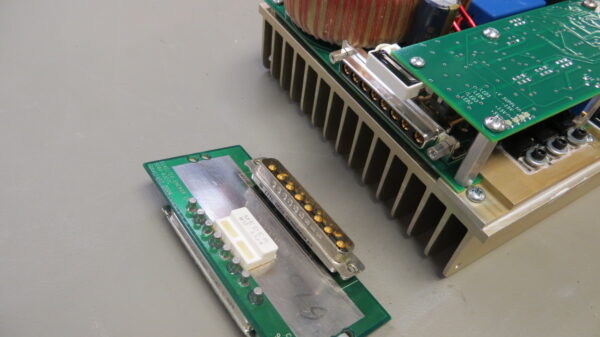
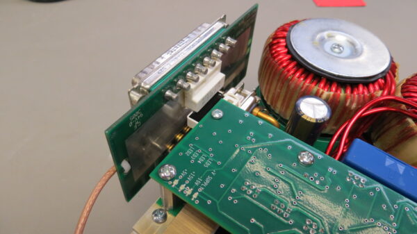
Attach the monitor board to the driver's output connector as in Figure 2 and Figure 3. The driver carries a magnetic reed switch on its top control card as a safety interlock; the white magnet on the monitor board must sit over that switch, as it does in Figure 3, or the driver will not enable.
3Connecting the stripline and the load
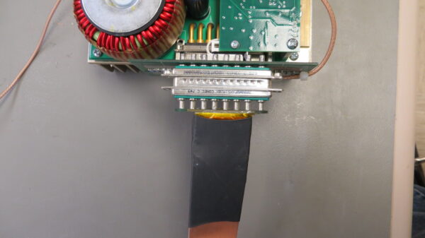
The stripline that carries the output to the load connects to the monitor board, not to the driver, so the sense resistor is in the loop (Figure 4). The demonstration load is an HPL-2400 high-power test load configured at 0.166 Ω, a custom value; the standard HPL-2400 values are 0.125, 0.25, 0.5, 1, 2, 5 and 10 Ω, with custom values available from the factory to match a specific diode. A laser diode is connected in exactly the same way, through the shortest stripline the mechanical layout allows.
4Oscilloscope setup
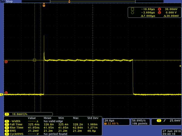
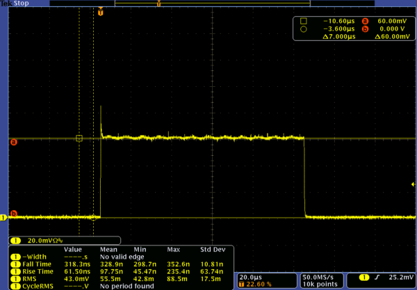
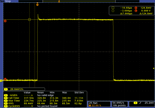
Connect the monitor cable to an oscilloscope input terminated in 50 Ω. Most oscilloscopes have the termination built in; if yours does not, use a 50 Ω BNC feedthrough terminator at the input. Set the vertical scale from the monitor's scale factor: with the PCA-9155 at 1 mV per A, 10 mV per division reads as 10 A per division, and 20 mV per division as 20 A per division. Choose the horizontal scale to show the whole pulse; for the 100 μs pulses in the captures below it is 20 μs per division.
5Captures at 30, 60 and 125 A
With everything connected, the PCO-6131 was triggered at 100 Hz with a 100 μs gate and the output current set to 30 A, 60 A and 125 A in turn (Figure 5, Figure 6, Figure 7). The cursor readout on each capture confirms the amplitude through the monitor's 1 mV per A scale. The rise-time trimpot on the PCO-6131 adjusts the leading edge from under 30 ns to over 2.5 μs; its setting during these captures was not recorded, so the rise-time readouts describe the setting used that day rather than the driver's fastest edge, and they differ from capture to capture.
6The PCO-7114 series, for installed units
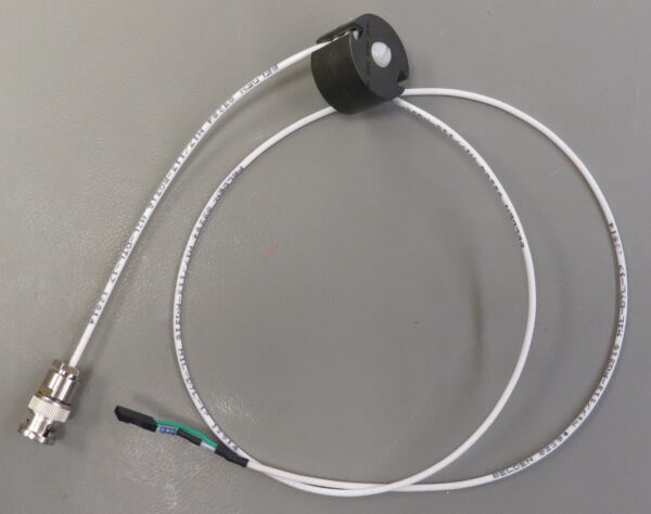
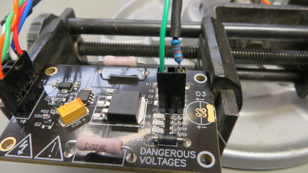
The PCO-7114-50-4 and PCO-7114-22-2 modules are discontinued, but many remain in service, and their current measurement differs from the boards above: the monitor is built into the module, on connector J2, and is read through the PCA-9140 current monitor cable (Figure 8). The cable carries a series 50 Ω resistor at the positive pin, which is the left-hand pin of J2 and connects to the center conductor (Figure 9).
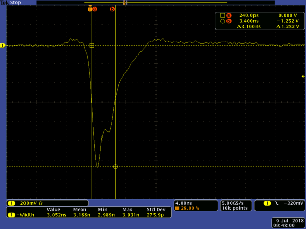
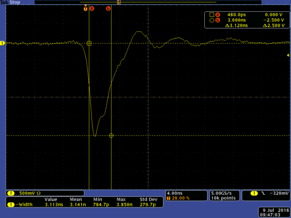
The PCO-7114-50-4 is a 50 A, 4 ns fixed-pulse-width driver that runs to 650 kHz depending on output current; its output current is set by the input high voltage. Its monitor scaling is 500 mV per 10 A (20 A per volt) into a 50 Ω terminated input. For the captures in Figure 10 and Figure 11 the oscilloscope was set to 4 ns per division with the module driving a shorted load, and the pulse width was measured at full width half maximum (FWHM).
7Questions
For help with a measurement, a monitor board or a load for a specific diode, contact info@berkeleynucleonics.com or 800-234-7858. The companion note Setting the PCO-6131 and PCO-6141 output current covers the setpoint controls that these measurements confirm.
Talk to an applications engineer
Tell us your load, pulse width and repetition rate. We will point you at the right driver or pulser, or tell you plainly if we do not have one.