
Connecting a fast current pulser to a laser diode
A current pulser rated for a nanosecond edge delivers that edge only if the loop between its output and the diode has very little inductance. This note puts numbers on the loop, shows the stripline connection and the adapter boards that make it practical, and gives the relation that says how far a pulse can be sent for a given rise time.

Photo: PCO-6131

1The loop sets the edge
Ranging, time-of-flight and digital communication work drives a laser diode with a narrow current pulse and a fast rising edge. The pulser produces the edge; the wiring between the pulser and the diode decides how much of it reaches the diode. The governing relation is the voltage an inductance needs to change its current:
Ten nanohenries of loop inductance, which is the order of a short hookup-wire loop, carrying a current that rises 100 A in 1 ns, needs 10 nH × 100 A / 1 ns = 1,000 V across it. A current-source driver has only its compliance voltage to spend. The PCO-6131, for example, is specified at 125 A with a rise time adjustable from under 30 ns and a diode forward voltage of 20 V maximum. Into the same 10 nH, a 125 A edge in 30 ns asks for 10 nH × 125 A / 30 ns = 42 V, twice the compliance available before the diode's own forward voltage is subtracted. The driver cannot supply it, so the edge slows until the loop's demand fits the headroom.
That gives a useful estimate of the fastest edge a given loop allows. With compliance headroom Vh (the compliance voltage less the diode forward voltage), the current cannot rise faster than di/dt = Vh / L, so a full-amplitude edge to current I takes at least
With 10 nH, 125 A and, as an assumption for the example, 15 V of headroom after 5 V across the diode, (2) gives about 83 ns: the loop, not the driver, would set the edge. The same relation says what the loop may be for the edge the application needs, which is the design question of Section 4.
2What stripline does
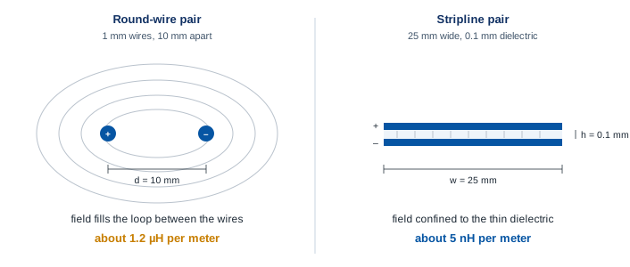
Two wide, flat conductors separated by a thin insulator carry a current out and back in the same place, so the magnetic field between them occupies almost no volume and the inductance per unit length is small. For a parallel-plate pair of width w and separation h, ignoring fringing, the inductance per meter is about μ0 h / w. Two round wires carry the same current with a large area between them, and their inductance per meter is about (μ0 / π) ln(d / r) for spacing d and wire radius r. Table 1 puts the two side by side for a one-foot run, and Figure 1 draws the difference.
| Connection | Geometry | Inductance per meter | For 0.3 m | Edge allowed at 125 A, 15 V |
|---|---|---|---|---|
| Round-wire pair | 1 mm diameter wires, 10 mm apart | about 1.2 μH | about 360 nH | about 3 μs |
| Stripline | 25 mm wide conductors, 0.1 mm dielectric | about 5 nH | about 1.5 nH | about 13 ns, inside the driver's own edge |
The factory-supplied stripline is the connection that preserves a sub-nanosecond to tens-of-nanoseconds edge over a few inches to a couple of feet. Adapters, clips and connectors in the current path each add a loop of their own; a clip lead can add more inductance than the whole stripline. If the supplied stripline is longer than needed, it can be shortened without ill effect. Do not extend it. Bending it is acceptable provided the two conductors are not separated, because separation increases the inductance, and it should be kept away from other conductors.
3Adapting the stripline to the diode
Laser diode packages rarely present two wide, flat terminals, so the practical step is a small two-layer printed circuit board that continues the stripline to the diode. One conductor of the stripline is soldered to each side of the board, which turns the board into an extension of the stripline (Figure 2). A radial-leaded diode mounts perpendicular to the board; an axial-leaded diode straddles its edge. Holes or cutouts are laid out to match the package, and a separate inexpensive board can be made for each package type.
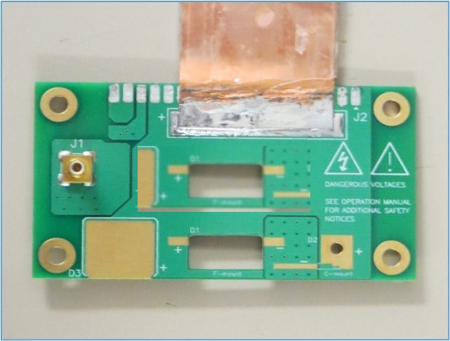
A DB-37 connector can be added so boards connect and disconnect from the stripline without soldering. The board in Figure 3 serves two purposes at once: it carries the diode and it provides a current monitor. Eight 2512-size surface-mount resistors are connected in parallel, chosen for low inductance, and the group is in series with the pulse output. A 49.9 Ω resistor in series with the monitor output matches a 50 Ω oscilloscope input, so the voltage across the sense group reads directly as current on the scope.

4Longer runs and the edge they allow
A pulse sometimes has to travel further than a stripline is supplied, for instance to a diode mounted 30 feet from the driver. The run can be made, but not with a one-nanosecond edge: (2) says the inductance of the run and the compliance headroom set the fastest edge the current can make, and a 30 ft run of any practical conductor pair carries hundreds of nanohenries. Rearranged, the loop that a required edge tolerates is L ≈ trise · Vh / I. At 125 A with 15 V of headroom, a 1 ns edge tolerates about 0.12 nH, a few millimeters of stripline, while a 1 μs edge tolerates about 120 nH, which a well-made 30 ft run can meet. The trade is always between the speed of the rising edge and the inductance that can be tolerated, and the relation puts a number on it before the cable is cut.
Where the run cannot be shortened and the edge cannot be relaxed, the remedy is to move the driver to the diode: the open-frame and enclosed OEM modules in the laser diode driver line exist so the output loop can be a few inches long inside the instrument.
5Seeing what the diode receives
The quickest check of a connection is to compare two captures on the oscilloscope: the driver's current monitor into a short at the output, and the same monitor with the diode connected through the wiring in question. Rounded edges in the second capture are the loop; ringing or a pulse that has collapsed into a damped sine wave means the loop is far too large for the edge being asked of it. The current-monitor accessories for each driver (the PCA-9155 for the PCO-6131 and the PCA-9150 for the PCO-6141, for example) make this a two-minute measurement; the note Measuring pulsed laser diode current on the PCO-6131 and PCO-6141 walks through the setup. The video above shows the connection being made.
6Drivers and a next step
The Directed Energy laser diode driver line runs from the PCX-7401 benchtop driver, adjustable from 1 mA, to the PCX-7500 family at 450 A, and includes fast OEM modules such as the PCO-7111, specified at 2 ns to 3.5 ns rise and fall. Every pulsed model ships with, or specifies, the low-inductance connection its edge needs. For applications that drive high-impedance loads rather than diodes, such as deflection plates, piezoelectric transducers or dielectric test samples, the high-voltage pulse generator line is the right family, and the BNC Academy offers an online course on high-voltage and high-current pulsers.
Send the diode or array, the current and compliance voltage it needs, the edge and width the application calls for, and the distance between driver and diode, and an applications engineer will say which driver and which connection fit. Contact info@berkeleynucleonics.com or 800-234-7858.
Talk to an applications engineer
Tell us your load, pulse width and repetition rate. We will point you at the right driver or pulser, or tell you plainly if we do not have one.