
Setting the PCO-6131 and PCO-6141 output current
The output current of the PCO-6131 and PCO-6141 is controlled by a small DC voltage from either an on-board source (local control) or an external source (external control). This note locates the four items involved and gives the procedure for each mode.

Photo: PCO-6141

1The four items involved
Setting the output current involves four items on the module:
- the I SET three-pin header, which selects the control mode;
- the CURRENT SET pot;
- the Current Setpoint input, pin 4 of J2;
- the Output Current Set Monitor output, pin 6 of J2.
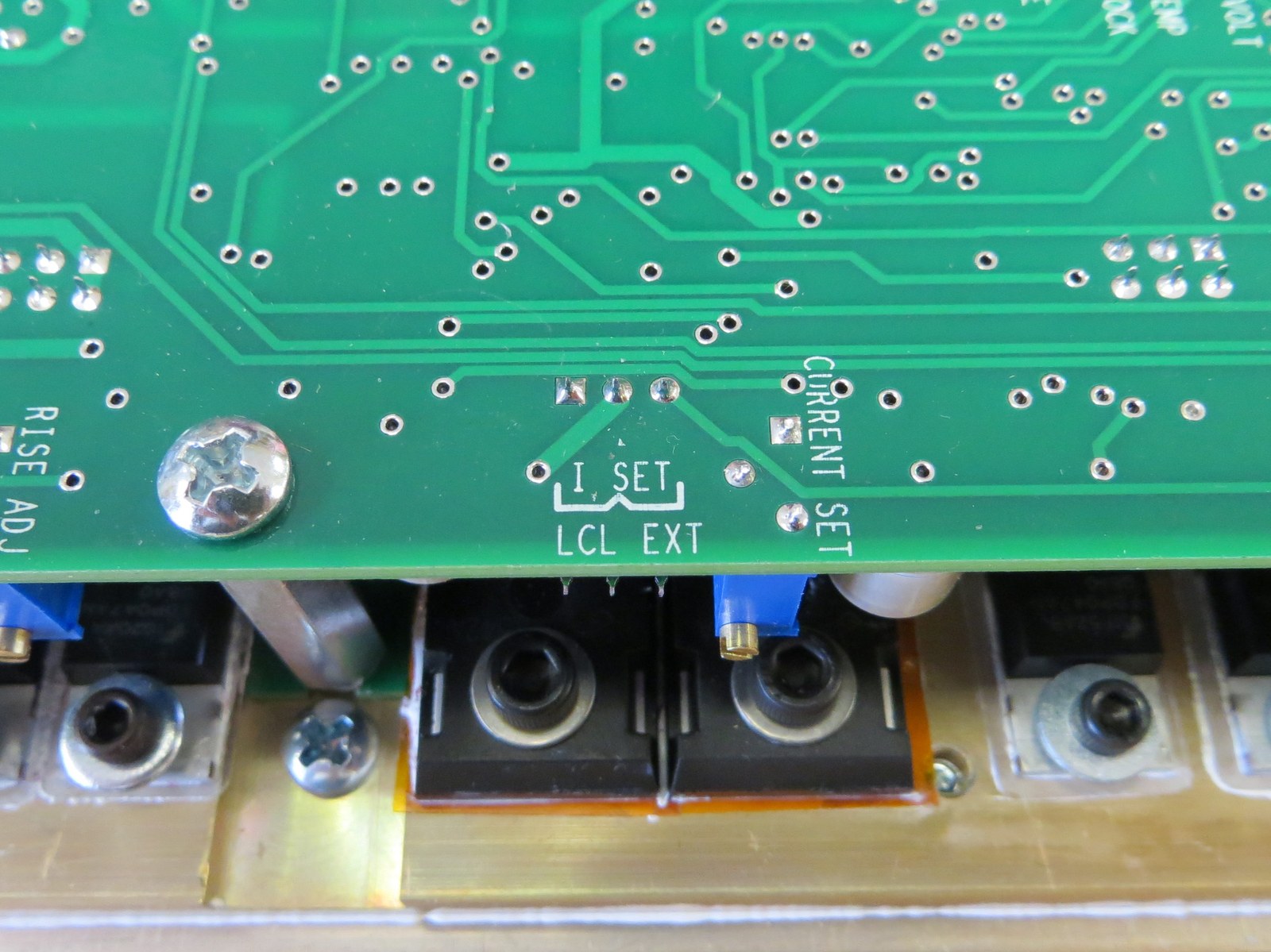
The I SET header is on the upper printed circuit board (Figure 1). The control mode is chosen by pushing the supplied shunt over two of its three pins.
2Local control
To place the unit in local control, push the shunt over the two pins marked LCL. In this mode a regulated internal +5 V source drives the CURRENT SET pot, and the pot alone sets the output current.
3External control
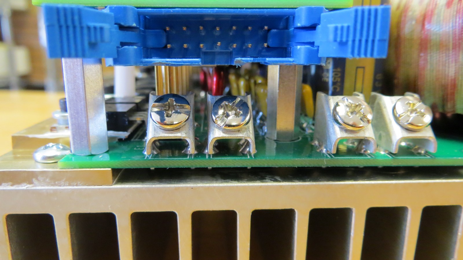
To place the unit in external control, push the shunt over the two pins marked EXT. In this mode the external supply connected to the Current Setpoint input (pin 4 of J2, Figure 2) drives the CURRENT SET pot. The output current is then controlled by both the amplitude of the external voltage and the position of the pot. The external setpoint range is 0 to 5 V or 0 to 10 V, jumper-selectable, as published in the PCO-6131 and PCO-6141 datasheets; do not exceed the selected range.
The CURRENT SET pot is active in both control modes. Zero current corresponds to the pot in its fully counterclockwise position.
4Reading the set current before the output is gated
Whenever the ENABLE input is high the unit is enabled and an internal loop current flows, even with the GATE input low. The voltage on pin 6 of J2, the Output Current Set Monitor, is proportional to that loop current: 10 mV per A into 50 Ω on the PCO-6131, and 20 mV per A into 50 Ω on the PCO-6141.
This is a high-impedance output intended for a digital multimeter or an oscilloscope. It is not part of the output pulse circuit, so it cannot be used to view output pulses. Its purpose is to let you measure and adjust the output current before bringing the GATE input high and turning the output on.
To see the actual output pulse, use the current monitor accessory for the driver: the PCA-9155 for the PCO-6131, at 1 mV per A into 50 Ω (1000 A per volt), or the PCA-9150 for the PCO-6141, at 5 mV per A into 50 Ω (200 A per volt). The companion note Measuring pulsed laser diode current on the PCO-6131 and PCO-6141 shows the measurement step by step.
5Questions
For help with a setpoint, a control interface or a board revision, contact info@berkeleynucleonics.com or 800-234-7858.
Talk to an applications engineer
Tell us your load, pulse width and repetition rate. We will point you at the right driver or pulser, or tell you plainly if we do not have one.